esm 2000 wiring diagram
Many thanks for visiting our website to locate 2000 Volvo S80 Engine Diagram. 22 front view and dimensions of esm-3710 temperature controller 32 electrical wiring diagram 33 view of the device label 35 temperature sensor input connection 352 ptc and ntc connection 353 pt-100 and pt-1000 connection 36 galvanic isolation test values of esm-3710 temperature controller 37 output connections 371 relay output.

Battery Charger Confusion Page 2 Caravan Batteries Battery Charging Caravan Talk
Cummins Shop Manual ISX QSX15 Series Engine Workshop Service Manual Troubleshooting and Repair ManualCONTENTS Introduction Familiarization Air intake system overview flow diagram Complete engine o.

. 3 4 6 Relay or SSR Driver Output L N Supply Voltage Input 230V 15 5060Hz 115V 15 5060Hz 24V 15 5060Hz 24V 15 5060Hz It must be determined in order. Download FREE diagrams schematics service manuals operating manuals and other useful information for a variety of products. HOW TO READ WIRING DIAGRAMS GI-10.
Please see more wiring amber you can see it in the gallery below. I personnally own a Fleetwood Heritage but am in the process of doing a van conversion for racing wife not keen on pride and joy getting taken to muddy offroad events access sometimes a prob tooBasically when i removed this from a salavaged sterling i stupidly forgot to. 1998 2001 FSR FTR FVR 2000 2001 FRR WT5500ENGINE.
Hi I have a 1992 Mercedes Benz 300E 26 with the M103 EngineIm Having some trouble with the AC. Need a vtec wiring diagram f20c s2000 s2ki honda forums engine performance 2008 system diagrams sheme ožičenja za avtomobile viper 5706v 2001 drl install andrew lavigne s website modifry ect installation s2k starter on retromodern usa headlights 2006 for cars ecu pinouts where can i get em tech forum discussion in kill switch own 03 the gauge cer Read More. Hopefully we provide this can be useful for you.
Currently we have 27502 Diagrams Schematics Datasheets and Service Manuals from 978 manufacturers totalling 1622 GB and the range is expanding all the time. Ab power distribution 22 3 fb chassis solenoids 27. Otherwise very easy to install the added benefit of the cooling fan will help protect the unit during my long trips into Spain.
Fa air dryer heated drain 26. 50 V 400 W 8 A for ohmic load. Cummins 2000 ISX QSX15 Repair Manual PDF.
2004 volvo s40 engine diagram unique volvo s80 timing mark diagram 2005 volvo engine diagram wiring circuit volvo wiring diagrams to p1800 plete. The EGR system module ESM is one of Fords latest EGR system for gasoline engines. Cummins Wiring Diagrams N14 Mpdf - Download as PDF File pdf Text File BLACK INDICATES RETURNS TO THE ECM AND GENERIC OEM WIRINGThe Cummins CELECT Engine ECM wiring diagram provides information for the correct servicing and troubleshooting of electrical systems and is essential for all mechanics carrying out repairs or maintenance on the.
Engine and emission control overall engine and emission basic control. 30 mA 12 V 35 OUTPUT 3 3. The maximum length for a single drop cable is 20 feet.
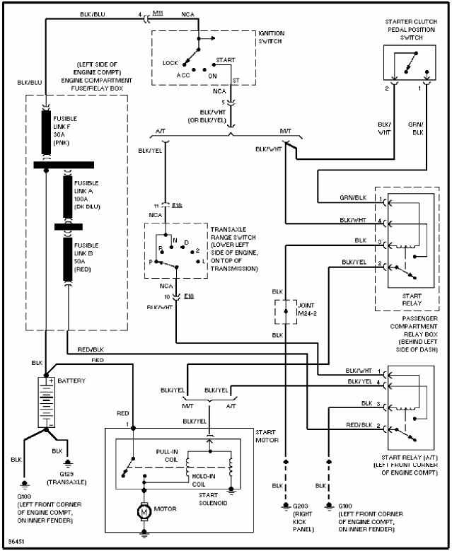
Wiring Diagrams and Trouble Diagnosis NGSC0002 When you read wiring diagrams refer to the following. Up to 2000 m. 2000 ELECTRICAL WIRING MANUAL MVP-ER 2000 Thomas Built Buses Inc.
It is an EGR valve EVR MAP and DPFE sensor rolled into one package. Wiring diagram toyota echo 2002 zufairihalim lexus gs450h hopinp lampadineantizanzare it yaris diagrams car electrical all for cars camry le steeting circuit carfusebox 99 05 fuse service repair manual free pdf s radio system diagramas de cableado para automóviles 1999 2005 verso by steve castillo issuu 2007 manualzz celica rx476 15 26 picclick uk stereo audio autoradio connector Read. I had to re-route some of the wiring and replace the Earth lead with a longer wire.
NMEA 2000 signals can be hampered by resistance which causes a reduction in voltage. Does anyone know were I could obtain a wiring diagram for the above P-I-S do not seem to be trading anymore. Though the DPFE sensor on an ESM is referred to as DPFE by the scan tool and also wiring diagrams it is not a traditional DPFE sensor as used on the older EGR system.
Check the wiring by comparing it to the wiring diagrams. Total current through all 3 contacts. 24 V 3 A for DC-13 Max.
Electrical Wiring Diagram 2 1 5 7 8-N -3700 ESM PN. 2 Installation removal Fig. 22 front view and dimensions of esm-3700 digital process indicator with alarm output 23 front view and dimensions of esm-3700 digital process indicator withoutalarm output 32 electrical wiring diagram 33 view of the device label 35 process input connection 351 process input connection of serial transmitter with current output loop powered.
Operating Conditions ForbiddenConditions. 1 Block diagram ESM-BA3. W 2000-04-01 om mru 2014 wiring diagram index 12v.
FSE01-ESM-C01pdf 368 pages Isuzu Commercial Truck FORWARD TILTMASTER Service Manual 6HK1-TC Engine 1998-2001 FSR FTR FVR 2000-2001 FRR 2000-2001 WT5500 This service manual contains diagnosis on-vehicle service wiring diagrams and component unit repair for 6HK1-TC engine. 250 V 2000 VA 8 A for ohmic load 250 V 3 A for AC-15 DC. - For SSR Output This Output exist in device with Alarm Output Max.
Hi Does anybody have the wiring diagram or details for the ESM 2000 and kt92gt2 control panel from a 2002 Sterling. 32 ELECTRICAL WIRING DIAGRAM 33 LABELS FOR ESM-7710 TEMPERATURE CONTROLLER WITH ONE RELAY 34 LABELS FOR ESM-7710 TEMPERATURE CONTROLLER WITH TWO RELAYS SUPPLY VOLTAGE INPUT CONNECTION OF THE DEVICE. FSE01-ESM-C01pdf 368 pages Isuzu Commercial Truck FORWARD TILTMASTER Service Manual 6HK1-TC Engine 1998-2001 FSR FTR FVR 2000-2001 FRR 2000-2001 WT5500 This service manual contains diagnosis on-vehicle service wiring diagrams and component unit repair for 6HK1-TC engine.
Name description page name description page aa power distribution 12 2. Check the safety switch used. I do have a wiring Diagram however this one is not showing a connection between the Auxiliary Fan Relay and the MAS RelayThe reason why I need it is because the Diagram I have Shows me 5 wires comming out of the Auxiliary relay and checking it there are only 4 wires and the one missing is the.
It is actually two separate MAP sensors. 1998 - 2001 FSR FTR FVR 2000 - 2001 FRR WT5500ENGINE. TIA _____ Information from ESET Smart Security version of virus signature database 4378 20090828 _____.
Ac-o key sw start charging. My ESM-2000 Power supply module had failed this replacement unit fitted nicely to the existing mounts. Spiral cable and wiring harnesses except SEAT BELT PRE-TENSIONER cov-ered with yellow insulation either just before the harness connectors or for the complete harness are related to the SRS.
If you require a longer cable run to connect an item such as a transducer or sea-surface temperature sensor use a T-junction to either at the end or the middle of the run to tie in 12-volt power.

How To Repair Esm2000
Hyundai Elantra Audio System Manual

How To Repair Esm2000

Pin On Conexiones

W220 S500 7gtronic Wiring Diagram For Rear Sam Mercedes Benz Forum

How To Repair Esm2000

How To Repair Esm2000

Pin On Electrical Wiring Diagram

Swift Charisma 2003 Water Pump Not Working Swift Caravans Caravan Talk

Wiring Diagram For Electric Scooter Electrical Wiring Diagram Trailer Wiring Diagram House Wiring

System Sensor Smoke Detector Wiring Diagram Best Wiring Diagram In 2021 Home Security Systems Wireless Home Security Systems Fire Alarm System
Wiring Diagram Of Motorcycle Ma 2000 Wiring Circuit Diagram Motorcycle Wiring Alarm System

Cec Esm 2000 2 Distribution Module Motorhome Accessories Diy Camper Caravan

New Perkins Generator Wiring Diagram Generator Transfer Switch Transfer Switch Electrical Circuit Diagram

Nissan Teana J31 01 2007 Repair Manual Download

How To Repair Esm2000

How To Repair Esm2000

How To Repair Esm2000
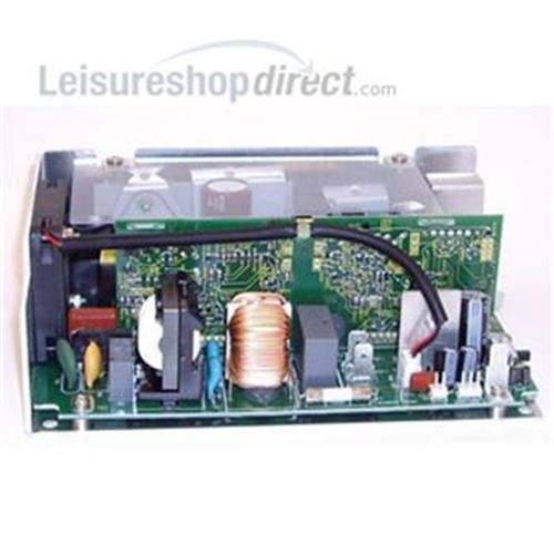
Cec Pcb For Plug In Systems Pm5 Esm Transformers Leisureshopdirect